3D Printing Conformal Molds
3D Printing Conformal Molds

MBFZ toolcraft combines conformal cooling with topology optimization in an efficient mold. Image: Richard Borge
Conformal molds have been a holy grail of additive manufacturing for decades. Compared with conventional molds’ straight-drilled channels, conformal injection molds have cooling channels that follow the contours of a part being molded. This allows heat to be removed faster so that factories can run more molding cycles per shift.
Recently, additive manufacturing firms have begun to offer cost-effective 3D-printed conformal inserts that enable conventional mold blocks to behave like conformal molds.
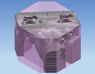 The mold’s properties were tested during design. Image: MBFZ toolcraft
MBFZ toolcraft of Georgensgmünd, Germany, has gone one better. The company has 3D printed an entire mold while using an AI technique, topology optimization, to slash mass by half. With less mass to heat and cool, the conformal mold reduced cycle times by 30 percent when compared to conventional options.
The mold’s properties were tested during design. Image: MBFZ toolcraft
MBFZ toolcraft of Georgensgmünd, Germany, has gone one better. The company has 3D printed an entire mold while using an AI technique, topology optimization, to slash mass by half. With less mass to heat and cool, the conformal mold reduced cycle times by 30 percent when compared to conventional options.
The 300-employee company relied on an integrated set of computer tools (Siemens NX), which integrates design, finite element analysis, and 3D production. This enabled MBFZ toolcraft to test the mold’s properties and build a plan virtually during design.
“We work with only one file along the process chain,” said Ralf Domider, the design engineer who headed the project. “There is less complexity. You can work in less time and have a lower error rate.”
Further Reading: 6 Innovative Ways to Use 3D Printing
As a result, MBFZ toolcraft was able to print a usable mold on its first try—for the same cost as a conventional mold.
 Ralf Domider, engineering and simulation in metal laser melting. Photo: MBFZ toolcraft
The project began when camera maker Leica submitted a mold for redesign. The 60-kg mold consisted of a variety of inserts, plates, and components to connect it to an injection molding machine.
Ralf Domider, engineering and simulation in metal laser melting. Photo: MBFZ toolcraft
The project began when camera maker Leica submitted a mold for redesign. The 60-kg mold consisted of a variety of inserts, plates, and components to connect it to an injection molding machine.
To optimize the topology, the team first applied a set of constraints. The design, for example, needed to show enough strength to handle high molding pressures and temperatures while also accounting for various connectors and clamping surfaces (for CNC finishing).
The topology optimization system ran a series of iterative calculations, ultimately eliminating mass while meeting those constraints. Domider used FEA analysis to validate the mold’s strength and behavior.
Further Reading: Laser Printer Evolves to 3D Printing
Then he added cooling channels. These had to be kept smaller than 8 mm because larger channels would collapse without supports. (Supports deep in those winding passage could not be machined away). Domider then simulated the mold’s thermal properties to ensure even heating and cooling, making design adjustments as he went along.
 Benedikt Altmann, engineering and simulation in additive manufacturing. Photo: MBFZ toolcraft
The hardest part of the project was 3D printing the mold, said Benedikt Altmann, who handles engineering and simulation for MBFZ toolcraft’s 3D metal printers. Laser metal printing involves high temperatures. The company needed to simulate the printing process to ensure the mold did not warp or distort during the build.
Benedikt Altmann, engineering and simulation in additive manufacturing. Photo: MBFZ toolcraft
The hardest part of the project was 3D printing the mold, said Benedikt Altmann, who handles engineering and simulation for MBFZ toolcraft’s 3D metal printers. Laser metal printing involves high temperatures. The company needed to simulate the printing process to ensure the mold did not warp or distort during the build.
The resulting mold was roughly the size of the original, but consisted of just two halves and weighed only 30 kg.
The customer was satisfied with results, and so was MBFZ toolcraft, Altmann said.
“The engineering went very fast, and our production time was reduced,” he said. “The overall costs of the additive manufacturing mold were about the same as those of a conventional mold, and the additive mold outperforms the conventional mold by a wide margin.”
Alan S. Brown is senior editor.
Learn More About Emerging Tech Awards 2019
Recently, additive manufacturing firms have begun to offer cost-effective 3D-printed conformal inserts that enable conventional mold blocks to behave like conformal molds.
The mold’s properties were tested during design. Image: MBFZ toolcraft
The 300-employee company relied on an integrated set of computer tools (Siemens NX), which integrates design, finite element analysis, and 3D production. This enabled MBFZ toolcraft to test the mold’s properties and build a plan virtually during design.
“We work with only one file along the process chain,” said Ralf Domider, the design engineer who headed the project. “There is less complexity. You can work in less time and have a lower error rate.”
Further Reading: 6 Innovative Ways to Use 3D Printing
As a result, MBFZ toolcraft was able to print a usable mold on its first try—for the same cost as a conventional mold.
Ralf Domider, engineering and simulation in metal laser melting. Photo: MBFZ toolcraft
To optimize the topology, the team first applied a set of constraints. The design, for example, needed to show enough strength to handle high molding pressures and temperatures while also accounting for various connectors and clamping surfaces (for CNC finishing).
The topology optimization system ran a series of iterative calculations, ultimately eliminating mass while meeting those constraints. Domider used FEA analysis to validate the mold’s strength and behavior.
Further Reading: Laser Printer Evolves to 3D Printing
Then he added cooling channels. These had to be kept smaller than 8 mm because larger channels would collapse without supports. (Supports deep in those winding passage could not be machined away). Domider then simulated the mold’s thermal properties to ensure even heating and cooling, making design adjustments as he went along.
Benedikt Altmann, engineering and simulation in additive manufacturing. Photo: MBFZ toolcraft
The resulting mold was roughly the size of the original, but consisted of just two halves and weighed only 30 kg.
The customer was satisfied with results, and so was MBFZ toolcraft, Altmann said.
“The engineering went very fast, and our production time was reduced,” he said. “The overall costs of the additive manufacturing mold were about the same as those of a conventional mold, and the additive mold outperforms the conventional mold by a wide margin.”
Alan S. Brown is senior editor.
Learn More About Emerging Tech Awards 2019
MBFZ toolcraft combines conformal cooling with topology optimization in an efficient mold. Image: Richard Borge
Related Content

Jul 31, 2025
10 Electric Cars with the Longest Range and Lowest Price in 2025
What's the best range electric car and which EV is cheapest in 2025? See who's in the lead on the electric vehicles list.

May 15, 2025
Origami Inspires Bendable 3D-Printed Ceramics
Multidisciplinary research brought together origami, materials science, and 3D printing to yield flexible ceramic structures.

Mar 27, 2025
3D Printing Meets High Performance in Czinger Hypercars
One of the fastest cars in the world, the Czinger 21C pushes the boundaries of performance.

Mar 10, 2025
Podcast: Inside the Engineering of a Czinger Hypercar
Chief engineer of Czinger Vehicles offers a look into the 3D printing technology shaping the future.