Steam Hammer – Predicting Transient Pipe Forces Accurately and Conservatively
Steam Hammer – Predicting Transient Pipe Forces Accurately and Conservatively
The best way forward is to go backward, as in, back to basics.
Sponsored by

When a valve closes in a steam system, a family of compression waves is generated upstream of the valve. What is meant by “family of waves”? When the valve first starts to close, the first compression wave is generated. As it continues to close, each incremental valve movement generates another incremental wave that travels into the disturbed flow field of the previously generated waves. When the valve reaches full closure a final wave is generated. These waves are referred to here as a “family” of waves. The family has a leading edge (from the initial valve movement) and a trailing edge (from the final valve movement when it comes to full closure).
When this wave family travels through direction changes such as elbows, it causes transient forces acting on the elbows. Engineers designing pipe systems must design for these forces or the pipe and/or pipe supports can fail.
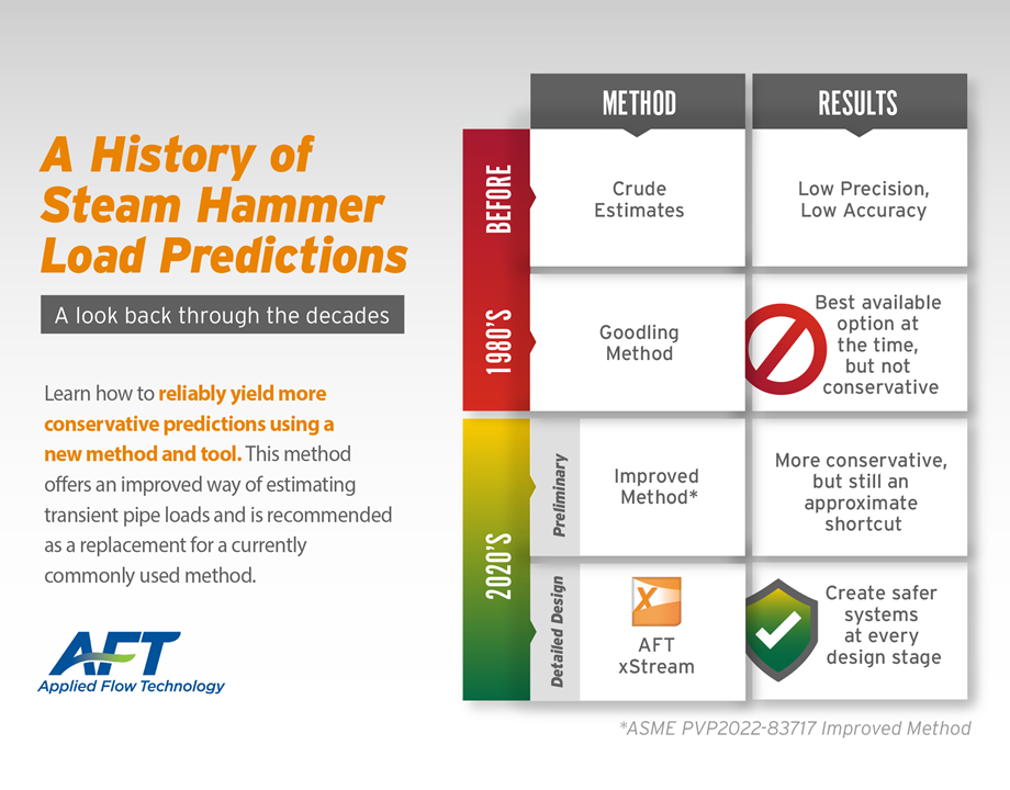
Predicting steam hammer pipe forces is quite complicated. As a result engineers have sought simplified methods believed to be conservative. It was recently shown at the ASME 2022 PVP Conference that the available methods are in fact not conservative. The details are given here in this paper: “A Critique of Steam Hammer Load Analysis Methods” (PVP2022-83715). In short, current methods ignore wave steepening whereby the back of the wave family travels faster than the front. The paper shows how wave steepening can result in transient pipe forces much higher than predicted by current methods. In this situation, the best way forward is to go backwards. More specifically, to go back to basics.
Back To Basics
Going back to basics here involves two steps.
- Predicting the transient behavior of the steam in the pipe system during the valve closure transient
- Using the Step 1 results to predict the transient forces on the pipe direction changes from the steam transient
What “basics” should we lean on? How about Newton’s Laws of Motion and the Laws of Thermodynamics?
Realize that using “the basics” does mean everything becomes easy. Sending humans to Mars on a rocket will also rely on the basics of Newton and Thermodynamics. The basic principles are pretty straightforward. The application will be very difficult!
Step 1: Predicting the transient behavior of the steam flow
This is a complicated task even though the basics are straightforward. The complicated part is solving the fundamental equations of transient compressible flow. Because it was so complicated, engineers have resorted to simplified methods. If the simplified methods are conservative, then that saves a lot of hard work on the complicated task of dealing with the fundamental equations.
The standard simplification is to use a form of the Joukowsky Equation as a proxy for solving the more complicated full equations. Goodling (1989) mapped out a simplified method for using Joukowsky on steam hammer.
However, valve closures in steam turbine lines are not instantaneous and thus using Joukowsky for finite valve closure times carries risk. Here is where gas transients behave differently than liquid transients.
When a liquid transient occurs, the acoustic liquid wave retains its shape over time and space – until a reflection point occurs. What this means is that it exerts the same force on a pipe section separated by elbows regardless of how far the elbows are from the source of the transient.
Gas transients are different. A gas transient wave deforms because of compressibility. A compression wave, which is what happens upstream of a closing valve, deforms in such a way that the back of the generated wave family catches the front. This means that the wave family steepens.
For example, consider the 2,000 ft (600 m) steam line in Fig. 1. The Turbine Stop Valve closes in 0.1 seconds. The wave takes about 1.25 seconds to travel the full length of pipe.
Fig. 2 shows how the pressure wave steepens with time as the wave moves to the left. These results are obtained with AFT xStreamTM.
One of the powerful aspects of AFT xStream is that it includes a complete mass, momentum and energy balance. Thus the basics are honored and employed. The equations it solves are those formulated by Moody (1990) as below.
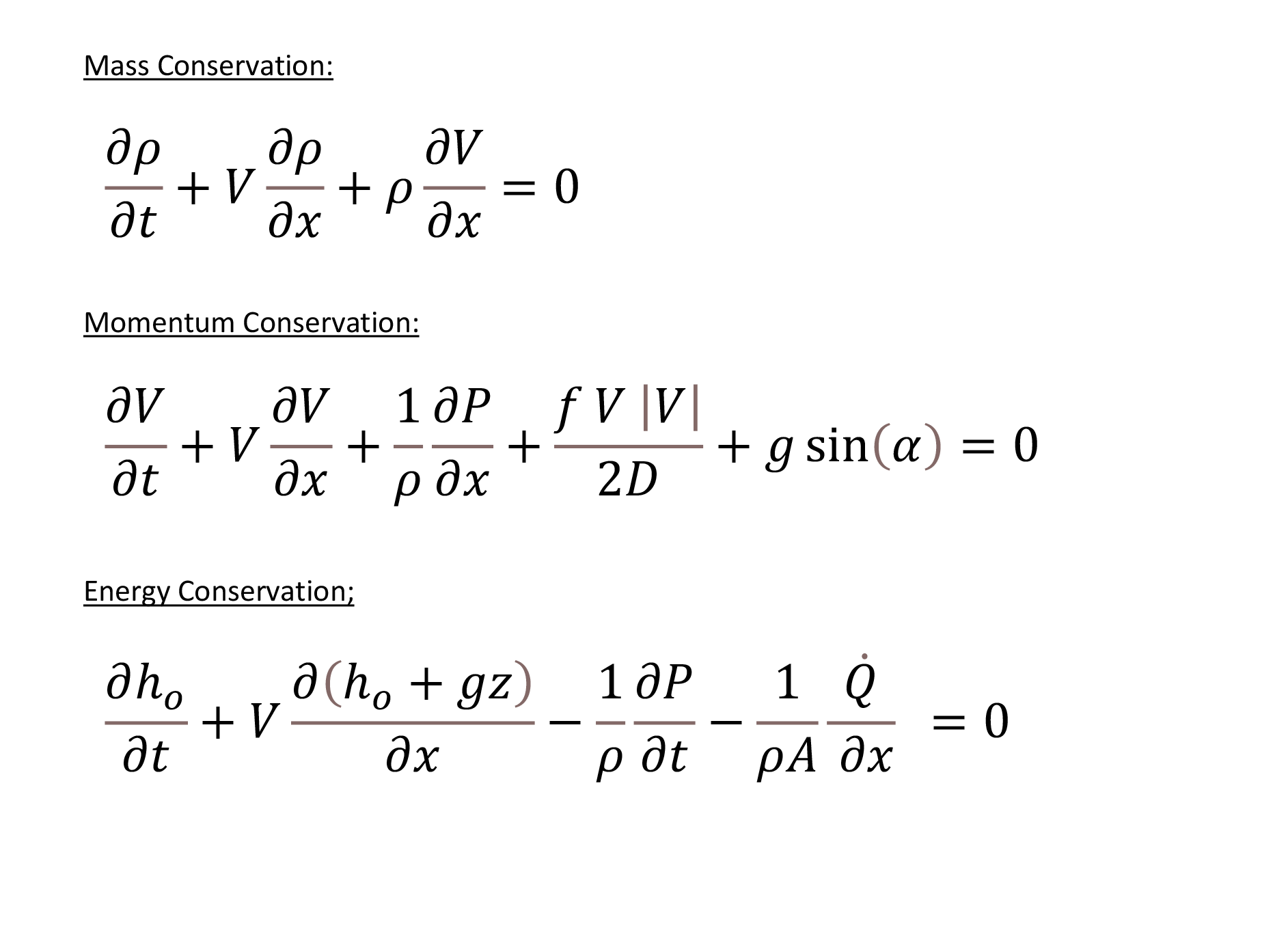
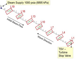 Figure 1. 2,000-ft (600 m) turbine steam pipe leg segments L1 trhough L19 all 40 ft (12 m) long.
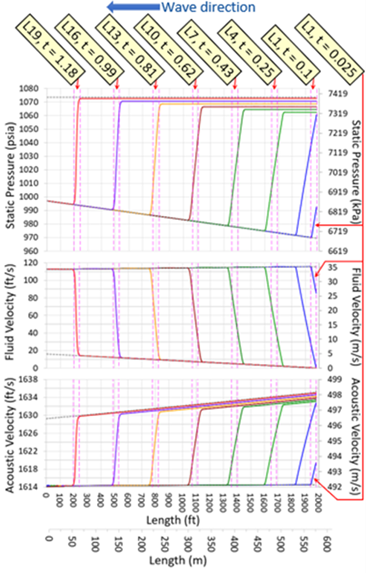 Figure 2. Predicted distribution of pressure, fluid velocity and acoustic velocity at various time at each pipe leg segment from Fig. 1. Results obtained with AFT xStream.
Step 2: Predicting transient forces in steam piping.
The basics of predicting transient forces in steam piping relies on Newton’s Second Law of Motion. Newton has several terms in it and steam piping engineers often focus only on the pressure terms and neglect the others. This is often an acceptable approximation but not always. In some cases the approximation is highly incorrect.
To ensure proper pipe loads are used for design, a complete force balance is recommended. The details of how to do this are discussed here: Applying Newton's Laws to Pipe Forces Caused by Fluid Transients is Tricky.
Figure 3 shows the predicted transient forces from the Fig. 1 model and Fig. 2 results. Conventional theory from Goodling predicts that all these forces are the same as those in L1, the smallest force. It is clearly seen that the forces in the other pipe legs are much higher than L1 and the Goodling prediction.
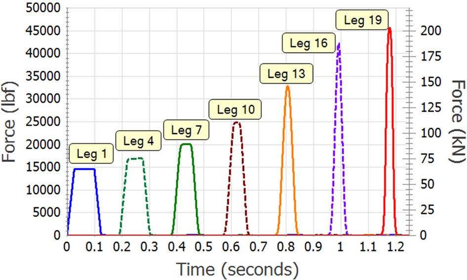 Figure 3. Transient forces on the pipe legs from Fig. 2 using the results in Fig. 2 and a complete force balance. Results obtained with AFT xStream.
Conclusion
A back to basics approach on steam hammer, while not simple, is complete and provides correct pressures and forces. Conventional methods such as Goodling are too simplified and are not reliably conservative.
References
Goodling, E. C., (1989), “Simplified Analysis of Steam Hammer Pipe Support Loads”, ASME/JSME Pressure Vessels and Piping Conference, Honolulu, Hawaii, USA, July 23-27, 1989, PVP Vol 165.
Moody, F. J., (1990), Introduction To Unsteady Thermofluid Mechanics, Wiley-Interscience, 1990.
Author
Trey Walters, PE, AFT President & Founder, ASME Fellow. Trey founded AFT in 1993. He holds a BSME (1985) and MSME (1986), both from the University of California, Santa Barbara, and is a registered Professional Engineer. He was the original developer of AFT Fathom, AFT Arrow and AFT Impulse and has taught hundreds of training classes on AFT’s software products in twelve countries across every populated continent. He worked previously for General Dynamics in cryogenic rocket design and Babcock & Wilcox in steam/water equipment design.
Related Content