MTC Develops Simulation App to Revolutionize Design for AM Parts
MTC Develops Simulation App to Revolutionize Design for AM Parts
The Manufacturing Technology Centre takes a new approach to part design and interdisciplinary research, using simulation and computational apps to support teams across the company.
Sponsored by
Case study provided by COMSOL
Additive manufacturing, also known as 3D printing, has been on the rise in recent years as a promising way to create parts with less material waste and to build shapes that were previously impossible to fabricate. The Manufacturing Technology Centre (MTC) in Coventry, UK, researches additive manufacturing techniques and supplies designs and prototypes to part producers in the industry. One additive manufacturing method they employ is laser powder bed fusion, which uses powder layers tens of microns thick to build parts layer by layer using a laser to fabricate a part with very fine geometrical details.
To verify the quality and performance of their additively manufactured parts, the MTC has used the COMSOL Multiphysics® software for virtual design testing, validation, and performance prediction. Over the past couple of years, they began building apps from COMSOL models that allowed them to share their analysis capabilities among different teams.
A New Approach to Part Design
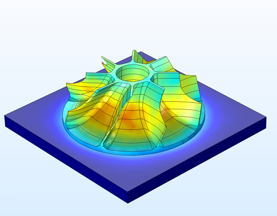
Laser powder bed fusion has certain advantages over other methods of fabrication, as higher accuracy and resolution can be achieved. One downside is that as the metal cools, deformations can occur. Thermal cycling can cause residual stresses during deposition, which causes distortions in the final part, as seen in Fig. 1.
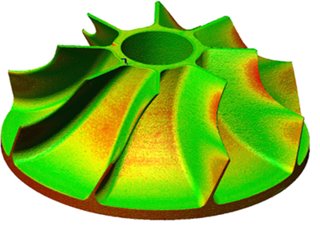 Fig. 1: Example of a distorted part, where the blades of an impeller have warped due to residual stresses. The red color indicates regions of high relative distortion.
The MTC team needed a way to get around the effects of thermal cycling. Borja Lazaro Toralles, team leader of MTC’s Physics Modelling team, said: “We created a simulation that predicts the stresses and deformation during a part build to give us a clear understanding of how it will distort during printing. Once we have this information, we can ‘invert’ the distortion in the part’s design, which allows us to account for the warping ahead of time so that the final product distorts into the shape we actually want.” This clever way of working backward from errors and building them directly into the designs has helped them create parts within the required tolerances more efficiently, as seen in Fig. 1.
Fig. 1: Example of a distorted part, where the blades of an impeller have warped due to residual stresses. The red color indicates regions of high relative distortion.
The MTC team needed a way to get around the effects of thermal cycling. Borja Lazaro Toralles, team leader of MTC’s Physics Modelling team, said: “We created a simulation that predicts the stresses and deformation during a part build to give us a clear understanding of how it will distort during printing. Once we have this information, we can ‘invert’ the distortion in the part’s design, which allows us to account for the warping ahead of time so that the final product distorts into the shape we actually want.” This clever way of working backward from errors and building them directly into the designs has helped them create parts within the required tolerances more efficiently, as seen in Fig. 1.
How would you create a simulation that allows you to test any shape made from any metal? Lazaro Toralles and his team first defined a modeling process that would predict the final shape of large parts. “Traditional additive manufacturing models are very detailed, down to the microstructure. But these are not suitable for simulating large part builds because of the computational cost,” Lazaro Toralles said.
“But we need to understand how an entire part will behave during printing. To circumvent this, we ‘lump’ the layers of the print build and impose an analytical temperature field based on experimental data. This reduces solving time but still gives an accurate solution.”
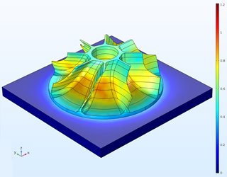 Fig. 2. Simulation results showing displacement in the impeller to predict the final part shape.
The simulation generates a grid to represent an approximate toolpath, and the temperature field is imposed on the grid points. The software then computes the stresses generated during deposition and predicts the final shape of the part shown in Fig. 2.
Fig. 2. Simulation results showing displacement in the impeller to predict the final part shape.
The simulation generates a grid to represent an approximate toolpath, and the temperature field is imposed on the grid points. The software then computes the stresses generated during deposition and predicts the final shape of the part shown in Fig. 2.
Spreading Predictive Capabilities
Once the simulation predicts the errors in a part, getting the information to the design team clearly and concisely was the next challenge. For this, Lazaro Toralles’ team built an app around their model, which allows the design engineers to run the simulation and see where designs need to be changed without having to understand the details of the simulation underneath. The app displays the simulation results — final shape, deformation, and stress levels for a given part, presented in Fig. 3.
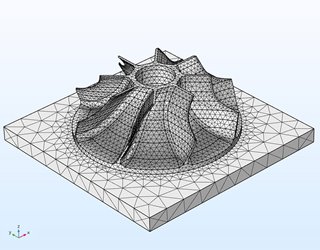 Fig. 3. The MTC app enables the user to make design adjustments and test changes in the simulation, but without showing the underlying model.
Simulation has changed the way teams work together at the MTC. “We [the simulation team] often use the app ourselves,” Lazaro Toralles added. “Once we built it, it was easier to make a few input changes in the app rather than go back to the original model.” On the use of simulation apps by other departments, Lazaro Toralles said, “Since the model consistently provided good results, everyone has found it helpful.”
Fig. 3. The MTC app enables the user to make design adjustments and test changes in the simulation, but without showing the underlying model.
Simulation has changed the way teams work together at the MTC. “We [the simulation team] often use the app ourselves,” Lazaro Toralles added. “Once we built it, it was easier to make a few input changes in the app rather than go back to the original model.” On the use of simulation apps by other departments, Lazaro Toralles said, “Since the model consistently provided good results, everyone has found it helpful.”
The simulation team’s work has been an essential part of helping the MTC establish a workflow that improves communication between the physics modeling team and the design team. This, ultimately, has changed the way they approach part design.
Borja Lazaro Toralles is team leader, Physics Modelling Department at MTC.
COMSOL Multiphysics is a registered trademark of COMSOL AB.
Learn more in our Bioengineeirng Special Report.
Additive manufacturing, also known as 3D printing, has been on the rise in recent years as a promising way to create parts with less material waste and to build shapes that were previously impossible to fabricate. The Manufacturing Technology Centre (MTC) in Coventry, UK, researches additive manufacturing techniques and supplies designs and prototypes to part producers in the industry. One additive manufacturing method they employ is laser powder bed fusion, which uses powder layers tens of microns thick to build parts layer by layer using a laser to fabricate a part with very fine geometrical details.
To verify the quality and performance of their additively manufactured parts, the MTC has used the COMSOL Multiphysics® software for virtual design testing, validation, and performance prediction. Over the past couple of years, they began building apps from COMSOL models that allowed them to share their analysis capabilities among different teams.
A New Approach to Part Design
Laser powder bed fusion has certain advantages over other methods of fabrication, as higher accuracy and resolution can be achieved. One downside is that as the metal cools, deformations can occur. Thermal cycling can cause residual stresses during deposition, which causes distortions in the final part, as seen in Fig. 1.
Fig. 1: Example of a distorted part, where the blades of an impeller have warped due to residual stresses. The red color indicates regions of high relative distortion.
Modeling for Complex and Varied Parts
How would you create a simulation that allows you to test any shape made from any metal? Lazaro Toralles and his team first defined a modeling process that would predict the final shape of large parts. “Traditional additive manufacturing models are very detailed, down to the microstructure. But these are not suitable for simulating large part builds because of the computational cost,” Lazaro Toralles said.
“But we need to understand how an entire part will behave during printing. To circumvent this, we ‘lump’ the layers of the print build and impose an analytical temperature field based on experimental data. This reduces solving time but still gives an accurate solution.”
Fig. 2. Simulation results showing displacement in the impeller to predict the final part shape.
Spreading Predictive Capabilities
Once the simulation predicts the errors in a part, getting the information to the design team clearly and concisely was the next challenge. For this, Lazaro Toralles’ team built an app around their model, which allows the design engineers to run the simulation and see where designs need to be changed without having to understand the details of the simulation underneath. The app displays the simulation results — final shape, deformation, and stress levels for a given part, presented in Fig. 3.
Fig. 3. The MTC app enables the user to make design adjustments and test changes in the simulation, but without showing the underlying model.
The simulation team’s work has been an essential part of helping the MTC establish a workflow that improves communication between the physics modeling team and the design team. This, ultimately, has changed the way they approach part design.
Borja Lazaro Toralles is team leader, Physics Modelling Department at MTC.
COMSOL Multiphysics is a registered trademark of COMSOL AB.
Learn more in our Bioengineeirng Special Report.
Related Content

5 Feedstocks for Biomass Energy Production
Apr 25, 2024
Wood, corn, even dung can heat homes and power industry. Discover energy from biomass.
Breakthrough Could Make for Long-Range EVs
Apr 16, 2024
A simple method could lead to electric vehicles that can go much father on a single charge, and batteries that last years longer than present technology.

5 Ballparks That Moved
Apr 4, 2024
Many ballparks feature quirks that cater only to baseball, but these stadiums were adaptable for football, soccer, and more.

Infographic: Green Buildings Make an Impact
Feb 27, 2024
Although square footage continues to grow, building sector emissions are steady, with the potential for more reductions ahead.