How to Connect Power Supplies in Parallel or Series for Increased Output Power
How to Connect Power Supplies in Parallel or Series for Increased Output Power
Explore the advantages of both parallel and series connections when connecting multiple power supplies.
Sponsored by
In some applications, the use of a single power supply may not be sufficient to provide the power required by the load. The reasons for using multiple power sources may include redundant operation to improve reliability or increased output power. When providing combined power, care must be taken to ensure power is delivered in a balanced manner by all of the supplies.
Redundant power supplies are a topology where the outputs of multiple power supplies are connected to increase the system’s reliability but not to increase the power output. Redundant configurations are typically designed to draw output current from only the primary power supplies and to draw current from the backup power supplies when a failure has occurred in one of the primary power supplies. Since drawing load current places stress on the components in a power supply, high reliability in the system is achieved when no current is drawn from the redundant supplies until there is an issue with one of the primary supplies.
The flow of power shown above depicts:
A common topology employed to increase output power is to connect the outputs of two or more supplies in parallel. In this configuration, each power supply delivers the required load voltage while connecting the supplies in parallel increases the available load current and thus the available load power.
This topology can be successfully implemented, but there are many considerations to ensure the efficiency of the configuration. For parallel configurations, power supplies with internal circuits are preferred as the internal circuits will improve the efficiency of the current sharing. If the power supplies used in a current sharing application do not have internal sharing circuits, then external methods must be used, which may be less efficient.
The primary concern is how evenly the load current is shared between the power supplies. The load current distribution is dependent upon both the design of the power supplies and the design of the external circuit and conductors used to connect the outputs of the supplies in parallel. It is almost always the case that identical supplies are used when connecting them in parallel due to the challenges of efficiently configuring the power supplies. However, it is possible to configure supplies in parallel with matching output voltages and non-matching maximum output currents.
The flow of power shown above depicts:
Another option to obtain greater power delivered to a load is to connect the outputs of multiple power supplies in series rather than in parallel. Some advantages of employing a series topology include near-perfect utilization of power delivery between the supplies, no need for configuration or sharing circuits, and tolerance to a large variety of application designs.
As mentioned previously, when connecting the outputs of supplies in parallel, each supply provides the required voltage, and the load current is shared between the supplies. In comparison, when the outputs of power supplies are connected in series, each supply provides the required load current, and the output voltage provided to the load will be the combination of the supplies in series.
It should be noted that when power supplies are configured with the outputs connected in series, the supplies do not need to have similar output characteristics. The load current will be limited to the lowest load current capability of any of the supplies in the configuration. The load voltage will be the sum of the output voltages of all of the supplies in the string.
A few limitations are imposed upon the power supplies when they are used in a series output configuration. One of the limitations is that the supplies’ output must be designed to tolerate the voltage offset due to the series configuration. This offset voltage will normally not be an issue, but the output voltages of ground-referenced power supplies cannot be stacked on the outputs of other supplies.
A second limitation is that the output of a supply can be subjected to a reverse voltage if the output is not active when the remaining outputs in the string are active. The reverse voltage concern can be easily resolved by placing a reverse-biased diode across the output of each supply. The breakdown voltage rating of the diode must be greater than the individual supply output voltage, and the diode current rating must be greater than the highest output current rating of any power supply in the series string.
Explore More: Achieving Electricity Diversity Through Waste to Energy
The flow of power shown above depicts:
Power supplies connected in parallel:
Bruce Rose is principal applications engineer at CUI Inc. During his many years in the electronics industry working in design, sales, and marketing, he has focused on analog circuits and power delivery.
Power Supplies Connected for Redundancy
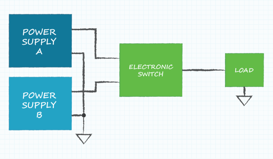
Redundant power supplies are a topology where the outputs of multiple power supplies are connected to increase the system’s reliability but not to increase the power output. Redundant configurations are typically designed to draw output current from only the primary power supplies and to draw current from the backup power supplies when a failure has occurred in one of the primary power supplies. Since drawing load current places stress on the components in a power supply, high reliability in the system is achieved when no current is drawn from the redundant supplies until there is an issue with one of the primary supplies.
The flow of power shown above depicts:
- Power supplies A and B are similar supplies; Vout and maximum Iout are the same
- The load voltage is equal to the supply voltage
- The maximum load current is equal to the maximum output current of one supply
- The electronic switch connects one of the supply outputs to the load
Power Supplies with Outputs Connected in Parallel
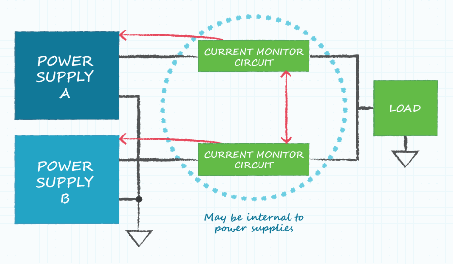
A common topology employed to increase output power is to connect the outputs of two or more supplies in parallel. In this configuration, each power supply delivers the required load voltage while connecting the supplies in parallel increases the available load current and thus the available load power.
This topology can be successfully implemented, but there are many considerations to ensure the efficiency of the configuration. For parallel configurations, power supplies with internal circuits are preferred as the internal circuits will improve the efficiency of the current sharing. If the power supplies used in a current sharing application do not have internal sharing circuits, then external methods must be used, which may be less efficient.
The primary concern is how evenly the load current is shared between the power supplies. The load current distribution is dependent upon both the design of the power supplies and the design of the external circuit and conductors used to connect the outputs of the supplies in parallel. It is almost always the case that identical supplies are used when connecting them in parallel due to the challenges of efficiently configuring the power supplies. However, it is possible to configure supplies in parallel with matching output voltages and non-matching maximum output currents.
The flow of power shown above depicts:
- Power supplies A and B need to have the same Vout; Iout maximum can be different
- The load voltage is equal to the supply voltage
- The maximum load current is equal to the sum of the maximum output current of both supplies
- The current monitor circuits balance the load current between the supplies
Power Supplies with Outputs Connected in Series
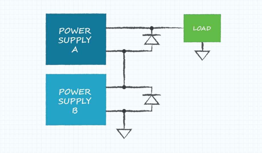
Another option to obtain greater power delivered to a load is to connect the outputs of multiple power supplies in series rather than in parallel. Some advantages of employing a series topology include near-perfect utilization of power delivery between the supplies, no need for configuration or sharing circuits, and tolerance to a large variety of application designs.
As mentioned previously, when connecting the outputs of supplies in parallel, each supply provides the required voltage, and the load current is shared between the supplies. In comparison, when the outputs of power supplies are connected in series, each supply provides the required load current, and the output voltage provided to the load will be the combination of the supplies in series.
It should be noted that when power supplies are configured with the outputs connected in series, the supplies do not need to have similar output characteristics. The load current will be limited to the lowest load current capability of any of the supplies in the configuration. The load voltage will be the sum of the output voltages of all of the supplies in the string.
A few limitations are imposed upon the power supplies when they are used in a series output configuration. One of the limitations is that the supplies’ output must be designed to tolerate the voltage offset due to the series configuration. This offset voltage will normally not be an issue, but the output voltages of ground-referenced power supplies cannot be stacked on the outputs of other supplies.
A second limitation is that the output of a supply can be subjected to a reverse voltage if the output is not active when the remaining outputs in the string are active. The reverse voltage concern can be easily resolved by placing a reverse-biased diode across the output of each supply. The breakdown voltage rating of the diode must be greater than the individual supply output voltage, and the diode current rating must be greater than the highest output current rating of any power supply in the series string.
Explore More: Achieving Electricity Diversity Through Waste to Energy
The flow of power shown above depicts:
- Power supplies A and B can have different Vout and Iout maximum
- The load voltage is equal to the sum of the supply output voltages
- The maximum load current is equal to the lower of the maximum output current of either supply
- The reverse bias diodes protect the outputs of the supplies
Power supplies connected in parallel:
- Poor power utilization due to the tolerance of current sharing control between the supplies
- A special circuit is required to control current sharing between the supplies
- Sensitive to design and construction of conductors connecting supplies in parallel
- Most easily designed with similar power supplies
- Efficient power utilization limited only by the output voltage accuracy of each supply
- No circuits required to control voltage or current sharing between the supplies
- No sensitivity to design or construction of conductors connecting supplies in series
- Easily designed with any combination of power supplies
Bruce Rose is principal applications engineer at CUI Inc. During his many years in the electronics industry working in design, sales, and marketing, he has focused on analog circuits and power delivery.
Related Content

Energy Blog: Noticeable Eclipse Impact on Electricity Sector
Apr 17, 2024

Breakthrough Could Make for Long-Range EVs
Apr 16, 2024
A simple method could lead to electric vehicles that can go much father on a single charge, and batteries that last years longer than present technology.

BatMan Breakthrough in EV Battery Manufacturing
Mar 28, 2024
Project looks to optimize battery charging speeds in EVs using laser ablation, advanced computational models, and materials characterization.

Community Voices: Is the Hydrogen Economy Finally Within Reach?
Mar 27, 2024
Guest contributor Deepa Poduval writes that a pathway to green hydrogen will help decarbonize hard-to-abate industries and help achieve net-zero ambitions.