How to Choose Power Adapter Input and Output Plugs
How to Choose Power Adapter Input and Output Plugs
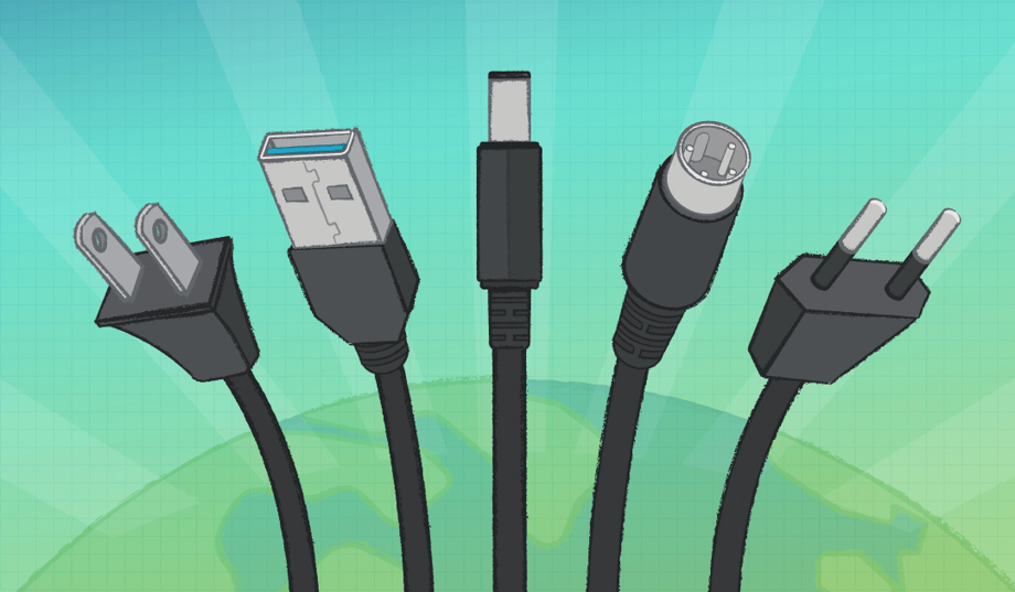
CUI’s latest blog discusses choosing correctly adapter input and output plugs depending on power requirements and geography.
Sponsored by
External power supplies employ many different input and output connector styles, and the connector selection is often based upon the input and output electrical and mechanical constraints associated with the application.
Let's explore common single-phase ac wall plugs (input) and dc power connectors (output) for wall plugs and desktop power supplies.
The selection of a proper wall plug for ac input voltage can be made by answering a few questions:
An appropriate ac input plug can be selected based upon industry standards after the above criteria have been determined. The standard wall plugs will have proper insulation for the rated voltages, and the contacts will be rated to work with specified maximum load currents. Unique mechanical construction related to the electrical specifications is used for the plugs and sockets to ensure that electrically incompatible plugs and sockets are not able to be used together.
Many desktop power supplies employ replaceable ac input power cords, while wall plug supplies have integrated ac input plugs. The ac input plug can be changed for desktop supplies that use replaceable power cords by selecting a power cord with the appropriate ac input plug. Some wall mount power supplies are designed with mechanically interchangeable ac input power blades to allow the same power supply to be used with different wall socket styles by changing the ac input blades to match the available wall socket.
.jpg?width=620&height=360&ext=.jpg) Ac power plug types.
Ac power plug types.
A standard set of plugs and sockets have been specified by the International Electrotechnical Commission (IEC) and are identified with letter designators. This is a helpful method to characterize connectors, but it should be understood this categorization is not a guarantee of compatibility between plugs and sockets with the same letter designator. An example of potential incompatibility is the plug Type A (used in North America, Central America, and Japan) often has a wide blade (Neutral) and a narrow blade (line) to provide for polarization of the plug when used in North America. However, the Type A plug used in Japan typically has two narrow blades; thus, the wide blade from North America will not fit in the narrow blade sockets found in Japan. However, the narrow blade plugs from Japan will fit in sockets from North America with either polarity orientation. CUI offers a World Plug and Input Voltage Guide for more information regarding international plug types.
.jpg?width=620&height=307&ext=.jpg) Japanese Type A plug with two narrow spades (left) and North American Type A plug with narrow and wide spades (right).
Japanese Type A plug with two narrow spades (left) and North American Type A plug with narrow and wide spades (right).
Single-phase ac input voltage delivered from the wall socket can involve either two or three conductors. Two conductors are required to deliver the voltage to the load while the third conductor is optional and connected to some form of ground potential. When included in the power delivery configuration, the ground conductor is present either to provide additional safety from contact with hazardous voltages in the load or to minimize conducted emissions from being unintentionally transferred from the load back to the wall socket.
Read our Infographic: Three Charts about the Electric Grid
International safety regulations allow for power supply designs with or without the ground conductor present (three or two conductor ac inputs, respectively). Additional information regarding this topic can be found on the CUI website with articles discussing Insulation, Isolation, and Working Voltage and What's the Difference Between Class 2 and Class II Power Supplies.
In many single-phase ac power applications, the power carrying conductors are labeled as Line and Neutral. The intention is that the voltage of the Neutral conductor is close to that of the ground and thus a "safer" voltage. As discussed above, the North American Type A power plug has a wide blade for the Neutral conductor, and thus the Neutral conductor can be identified at the power supply's input.
Not many designs of electronic products take advantage of this feature, as it is viewed as too easy to have an error in the construction of the power delivery or load systems and end up with a reversal of the Line and Neutral conductors. It should be noted that even though the Neutral conductor may nominally be at ground potential, the Neutral conductor is not to be used as a safety ground. The safety ground conductor, if employed, is not to be used as the Neutral return for Line power.
In some single-phase ac power applications, both powers carrying conductors are "hot" and at opposite polarity relative to the ground potential. These conductors are often then labeled as Line 1 and Line 2. A Neutral conductor is not included if Line 1 and Line 2 conductors are used to deliver power from the wall socket to the power supply's input.
Dc plugs for the output voltages from power supplies are not as standardized as are the ac input plugs. To limit the scope of this discussion, we will describe only some of the more common dc output plug styles: barrel connectors, DIN connectors, and USB connectors.
The table below lists some of the features associated with the three styles of dc output power plugs which we will discuss.
.jpg?width=687&height=197&ext=.jpg)
Perhaps the most common type of dc power plug is the barrel style. This style of plug provides a benefit in that it does not require a specific orientation when inserting it into the matching jack. Another advantage of the barrel plug is it has loose mechanical tolerances and thus is easy and inexpensive to manufacture.
Recommended for You: Renewable-Heavy Grids Need Watts in Store
The standard barrel plug is constructed with two concentric metal sleeves (barrels) that are separated by an insulator. The diameters of the inner or outer sleeves have been standardized, as has the length of the barrel so that it is possible to select a jack to mate to the plug properly.
.jpg?width=620&height=252&ext=.jpg) Barrel Plug with 2.1 mm inner diameter, 5.5 mm outer diameter, 9.5 mm barrel length.
Barrel Plug with 2.1 mm inner diameter, 5.5 mm outer diameter, 9.5 mm barrel length.
The mate to the barrel plug is a barrel jack with a pin and a cantilevered spring. The pin diameter of the jack is selected slightly smaller than that of the inner sleeve of the mating plug. The body of the jack will have a hole with a diameter that is somewhat larger than that of the outer sleeve of the matching plug. The depth of the hole in the body of the jack will be specified to be approximately the same dimension as the length of the sleeves of the plug.
.jpg?width=620&height=186&ext=.jpg) Barrel Jack
Barrel Jack
The mechanical relationships between the barrel plug and jack create the electrical connections of a barrel connector. The center pin of the jack is a loose fit within the center sleeve of the plug, and a cantilevered spring is attached to the plug's body. One of the electrical connections in the barrel connector is due to the cantilevered spring pushing against the outer sleeve of the plug. The second electrical connection in the barrel connector comes from the force of the cantilevered spring against the outer sleeve, causing the inner sleeve of the plug to be pushed against the center pin in the jack.
.jpg?width=620&height=206&ext=.jpg) Barrel plug and jack electrical connections.
Barrel plug and jack electrical connections.
The loose mechanical tolerances and low cost of barrel connectors make them appropriate for many applications, but these same characteristics can cause application issues. The gap between the non-mated cantilevered spring and the center pin on the jack, as well as the spring constant of the cantilevered spring, are seldom provided by the vendor of the jack. This lack of specifications makes determining the mechanical insertion or retention forces between the plug and the jack difficult.
Barrel connector locking designs are often specified if ensuring a robust mechanical connection is required between the plug and the jack. Two common locking barrel connector designs are a bayonet-style and a threaded style. The threaded style of locking connector is perhaps the more popular one. In the threaded locking barrel connector, the plug employs a floating nut (most commonly 5/16-32 thread) which will screw properly onto most panel mount barrel jacks.
.jpg?width=620&height=176&ext=.jpg) Threaded and twist locking barrel connectors.
Threaded and twist locking barrel connectors.
One of the important parameters for an electrical connector is the current rating of the contacts. The contact area and the mechanical force of the contact are two primary factors, which determine the current rating for electrical contact. In a barrel connector, the force of the contact is determined by the cantilevered spring, while the area of the contact is a function of the shape of the face of the spring and the difference in shape of the inner sleeve and the center pin. The current ratings for barrel connector contacts are relatively low due to the light force of the spring and the small areas of contact.
Editor’s Pick: Largest Hydroelectric Dam on Each Continent
While a large range of dimensions exists for both the inner and outer shield diameters for barrel connectors, some common pairs of dimensions are available as standard configurations. Perhaps the two most common dimension pairs are outer sleeve diameter of 5.5 mm, inner sleeve diameter of 2.1 mm, outer sleeve diameter of 5.5 mm, and inner sleeve diameter of 2.5 mm. Product designers may choose one of the more common sets of connector dimensions so that plugs and jacks are readily available, or they may choose a less common set of dimensions so that the connector pair is less likely to be interchanged with other products available in the market.
.jpg?width=620&height=284&ext=.jpg) CUI’s standard barrel plug offering: (top) outer diameter (middle) inner diameter (bottom) CUI part number designation.
CUI’s standard barrel plug offering: (top) outer diameter (middle) inner diameter (bottom) CUI part number designation.
With a barrel connector, the decision needs to be made regarding the polarity applied to the two concentric sleeves. By common convention, the shielded inner conductor is the positive polarity, and the exposed outer sleeve is at ground potential. This convention has been adopted to minimize the possibility of shorting the plug if it accidentally comes into contact with exposed grounded conductors. When using an unfamiliar power supply with a barrel plug, care should be exercised. Although the convention is for the outer sleeve to be at ground potential, there are many designs with the polarity of the sleeves reversed.
.jpg?width=620&height=136&ext=.jpg) Barrel plug polarity symbols.
Barrel plug polarity symbols.
Barrel plugs are available with the cord either entering the plug in-line (axial) or at a right-angle direction (radial). The in-line configuration is the most common as it is perhaps easier to manufacture and insert the plug into the jack. The right-angle configuration provides advantages in certain applications, such as when it is desired for the cord associated with the plug to lay alongside the side of the case or chassis in which the jack is mounted. Having the cable alongside the case or chassis can make the footprint of the product smaller and can also enable the cable to be captured in a clip on the case or chassis. Another situation in which the right-angle plug is of benefit is if there is concern that the plug may be unintentionally disconnected due to tension applied by the cable. If tension is applied to the cable with a right-angle plug, there will be a torque applied to the plug-jack mechanical connection, and it will thus be more difficult to separate the connection.
.jpg?width=620&height=207&ext=.jpg) Straight and right-angle barrel plugs.
Straight and right-angle barrel plugs.
While barrel connectors are perhaps the most common style used with low and moderate power level power supplies, DIN connectors are often used when higher electrical current capacity is required than can easily be supported by barrel connectors.
The DIN name is based upon the original German standards organization (Deutsches Institut fur Normung) and is now defined by IEC 60130-9. There are many configurations of DIN connectors available, but in this discussion, we are concerned only with the 4-pin power DIN connectors. It is difficult to find mechanical specifications for the power DIN connector, but it is reasonable to assume that connectors labeled as 4-pin power DIN connectors are compatible with each other. Like barrel connectors, power DIN connectors are available with a locking nut to prevent unintentional disconnect of the plug from the jack.
.jpg?width=620&height=285&ext=.jpg) DIN power plug and jack.
DIN power plug and jack.
While USB connectors were initially developed to deliver both power and digital signals, the wide acceptance of the USB mechanical connector and electrical power levels has led to many power-only applications. The USB Type-A connector is available in multiple configurations (standard, mini, micro, etc.) and, by convention, is used to deliver 5 V at a maximum load current of 2 A (10 W). A minor but sometimes frustrating limitation of the USB Type-A connectors is the plug and receptacle must be in the correct orientation (right-side up versus upside-down) before they can be mated.
The USB Type-C connector has been developed as a more compact, higher power, and higher digital signal speed improvement to the earlier Type-A connector. The specifications for the Type-C connector are a maximum of 20 V and 5 A (100 W). Although the USB connectors can be used to deliver output voltage levels other than 5 V, it is prudent for power delivery applications to provide only 5 V as the initial output voltage not to cause damage to products with USB receptacles. A means of exception to the previous statement regarding only 5 V from USB connectors is the USB forum has defined USB Power Delivery and Programmable Power Supply specifications which allow a power supply and load to negotiate for output voltages between 5 V and 20 V.
.jpg?width=620&height=142&ext=.jpg) USB connectors
USB connectors
The power industry has created and implemented standard plugs and sockets to transfer ac wall power from the power distribution system to power supplies. These standards are easy to implement, and there are few applications for which deviating from the standards is beneficial. The plugs and jacks available for the transfer of dc power from the power supply to the load afford the designer many more choices and fewer standards than the ac input power. Care should be taken to ensure that the dc connectors have the proper voltage and current rating for the application. Many power supply vendors, such as CUI, have technical and sales support staff who can provide advice regarding the selection of ac and dc connectors for power supply applications.
Bruce Rose is principal applications engineer at CUI Inc. During his many years in the electronics industry working in design, sales, and marketing, and he has focused on analog circuits and power delivery.
Let's explore common single-phase ac wall plugs (input) and dc power connectors (output) for wall plugs and desktop power supplies.
Selecting Plugs and Cords for Ac Input
The selection of a proper wall plug for ac input voltage can be made by answering a few questions:
- In what regions and/or countries will the power supply be used?
- What is the ac input voltage?
- What is the maximum ac input current?
- Does the application require an ac input ground?
An appropriate ac input plug can be selected based upon industry standards after the above criteria have been determined. The standard wall plugs will have proper insulation for the rated voltages, and the contacts will be rated to work with specified maximum load currents. Unique mechanical construction related to the electrical specifications is used for the plugs and sockets to ensure that electrically incompatible plugs and sockets are not able to be used together.
Many desktop power supplies employ replaceable ac input power cords, while wall plug supplies have integrated ac input plugs. The ac input plug can be changed for desktop supplies that use replaceable power cords by selecting a power cord with the appropriate ac input plug. Some wall mount power supplies are designed with mechanically interchangeable ac input power blades to allow the same power supply to be used with different wall socket styles by changing the ac input blades to match the available wall socket.
Ac power plug types.
A standard set of plugs and sockets have been specified by the International Electrotechnical Commission (IEC) and are identified with letter designators. This is a helpful method to characterize connectors, but it should be understood this categorization is not a guarantee of compatibility between plugs and sockets with the same letter designator. An example of potential incompatibility is the plug Type A (used in North America, Central America, and Japan) often has a wide blade (Neutral) and a narrow blade (line) to provide for polarization of the plug when used in North America. However, the Type A plug used in Japan typically has two narrow blades; thus, the wide blade from North America will not fit in the narrow blade sockets found in Japan. However, the narrow blade plugs from Japan will fit in sockets from North America with either polarity orientation. CUI offers a World Plug and Input Voltage Guide for more information regarding international plug types.
Japanese Type A plug with two narrow spades (left) and North American Type A plug with narrow and wide spades (right).
Ac Input Power; Two or Three Conductors
Single-phase ac input voltage delivered from the wall socket can involve either two or three conductors. Two conductors are required to deliver the voltage to the load while the third conductor is optional and connected to some form of ground potential. When included in the power delivery configuration, the ground conductor is present either to provide additional safety from contact with hazardous voltages in the load or to minimize conducted emissions from being unintentionally transferred from the load back to the wall socket.
Read our Infographic: Three Charts about the Electric Grid
International safety regulations allow for power supply designs with or without the ground conductor present (three or two conductor ac inputs, respectively). Additional information regarding this topic can be found on the CUI website with articles discussing Insulation, Isolation, and Working Voltage and What's the Difference Between Class 2 and Class II Power Supplies.
Variations in 2-conductor Single-phase Power
In many single-phase ac power applications, the power carrying conductors are labeled as Line and Neutral. The intention is that the voltage of the Neutral conductor is close to that of the ground and thus a "safer" voltage. As discussed above, the North American Type A power plug has a wide blade for the Neutral conductor, and thus the Neutral conductor can be identified at the power supply's input.
Not many designs of electronic products take advantage of this feature, as it is viewed as too easy to have an error in the construction of the power delivery or load systems and end up with a reversal of the Line and Neutral conductors. It should be noted that even though the Neutral conductor may nominally be at ground potential, the Neutral conductor is not to be used as a safety ground. The safety ground conductor, if employed, is not to be used as the Neutral return for Line power.
In some single-phase ac power applications, both powers carrying conductors are "hot" and at opposite polarity relative to the ground potential. These conductors are often then labeled as Line 1 and Line 2. A Neutral conductor is not included if Line 1 and Line 2 conductors are used to deliver power from the wall socket to the power supply's input.
Selecting Plugs for Dc Output
Dc plugs for the output voltages from power supplies are not as standardized as are the ac input plugs. To limit the scope of this discussion, we will describe only some of the more common dc output plug styles: barrel connectors, DIN connectors, and USB connectors.
The table below lists some of the features associated with the three styles of dc output power plugs which we will discuss.
Barrel Connectors
Perhaps the most common type of dc power plug is the barrel style. This style of plug provides a benefit in that it does not require a specific orientation when inserting it into the matching jack. Another advantage of the barrel plug is it has loose mechanical tolerances and thus is easy and inexpensive to manufacture.
Recommended for You: Renewable-Heavy Grids Need Watts in Store
The standard barrel plug is constructed with two concentric metal sleeves (barrels) that are separated by an insulator. The diameters of the inner or outer sleeves have been standardized, as has the length of the barrel so that it is possible to select a jack to mate to the plug properly.
Barrel Plug with 2.1 mm inner diameter, 5.5 mm outer diameter, 9.5 mm barrel length.
The mate to the barrel plug is a barrel jack with a pin and a cantilevered spring. The pin diameter of the jack is selected slightly smaller than that of the inner sleeve of the mating plug. The body of the jack will have a hole with a diameter that is somewhat larger than that of the outer sleeve of the matching plug. The depth of the hole in the body of the jack will be specified to be approximately the same dimension as the length of the sleeves of the plug.
Barrel Jack
The mechanical relationships between the barrel plug and jack create the electrical connections of a barrel connector. The center pin of the jack is a loose fit within the center sleeve of the plug, and a cantilevered spring is attached to the plug's body. One of the electrical connections in the barrel connector is due to the cantilevered spring pushing against the outer sleeve of the plug. The second electrical connection in the barrel connector comes from the force of the cantilevered spring against the outer sleeve, causing the inner sleeve of the plug to be pushed against the center pin in the jack.
Barrel plug and jack electrical connections.
The loose mechanical tolerances and low cost of barrel connectors make them appropriate for many applications, but these same characteristics can cause application issues. The gap between the non-mated cantilevered spring and the center pin on the jack, as well as the spring constant of the cantilevered spring, are seldom provided by the vendor of the jack. This lack of specifications makes determining the mechanical insertion or retention forces between the plug and the jack difficult.
Barrel connector locking designs are often specified if ensuring a robust mechanical connection is required between the plug and the jack. Two common locking barrel connector designs are a bayonet-style and a threaded style. The threaded style of locking connector is perhaps the more popular one. In the threaded locking barrel connector, the plug employs a floating nut (most commonly 5/16-32 thread) which will screw properly onto most panel mount barrel jacks.
Threaded and twist locking barrel connectors.
One of the important parameters for an electrical connector is the current rating of the contacts. The contact area and the mechanical force of the contact are two primary factors, which determine the current rating for electrical contact. In a barrel connector, the force of the contact is determined by the cantilevered spring, while the area of the contact is a function of the shape of the face of the spring and the difference in shape of the inner sleeve and the center pin. The current ratings for barrel connector contacts are relatively low due to the light force of the spring and the small areas of contact.
Editor’s Pick: Largest Hydroelectric Dam on Each Continent
While a large range of dimensions exists for both the inner and outer shield diameters for barrel connectors, some common pairs of dimensions are available as standard configurations. Perhaps the two most common dimension pairs are outer sleeve diameter of 5.5 mm, inner sleeve diameter of 2.1 mm, outer sleeve diameter of 5.5 mm, and inner sleeve diameter of 2.5 mm. Product designers may choose one of the more common sets of connector dimensions so that plugs and jacks are readily available, or they may choose a less common set of dimensions so that the connector pair is less likely to be interchanged with other products available in the market.
CUI’s standard barrel plug offering: (top) outer diameter (middle) inner diameter (bottom) CUI part number designation.
With a barrel connector, the decision needs to be made regarding the polarity applied to the two concentric sleeves. By common convention, the shielded inner conductor is the positive polarity, and the exposed outer sleeve is at ground potential. This convention has been adopted to minimize the possibility of shorting the plug if it accidentally comes into contact with exposed grounded conductors. When using an unfamiliar power supply with a barrel plug, care should be exercised. Although the convention is for the outer sleeve to be at ground potential, there are many designs with the polarity of the sleeves reversed.
Barrel plug polarity symbols.
Barrel plugs are available with the cord either entering the plug in-line (axial) or at a right-angle direction (radial). The in-line configuration is the most common as it is perhaps easier to manufacture and insert the plug into the jack. The right-angle configuration provides advantages in certain applications, such as when it is desired for the cord associated with the plug to lay alongside the side of the case or chassis in which the jack is mounted. Having the cable alongside the case or chassis can make the footprint of the product smaller and can also enable the cable to be captured in a clip on the case or chassis. Another situation in which the right-angle plug is of benefit is if there is concern that the plug may be unintentionally disconnected due to tension applied by the cable. If tension is applied to the cable with a right-angle plug, there will be a torque applied to the plug-jack mechanical connection, and it will thus be more difficult to separate the connection.
Straight and right-angle barrel plugs.
DIN Connectors
While barrel connectors are perhaps the most common style used with low and moderate power level power supplies, DIN connectors are often used when higher electrical current capacity is required than can easily be supported by barrel connectors.
The DIN name is based upon the original German standards organization (Deutsches Institut fur Normung) and is now defined by IEC 60130-9. There are many configurations of DIN connectors available, but in this discussion, we are concerned only with the 4-pin power DIN connectors. It is difficult to find mechanical specifications for the power DIN connector, but it is reasonable to assume that connectors labeled as 4-pin power DIN connectors are compatible with each other. Like barrel connectors, power DIN connectors are available with a locking nut to prevent unintentional disconnect of the plug from the jack.
DIN power plug and jack.
USB Connectors
While USB connectors were initially developed to deliver both power and digital signals, the wide acceptance of the USB mechanical connector and electrical power levels has led to many power-only applications. The USB Type-A connector is available in multiple configurations (standard, mini, micro, etc.) and, by convention, is used to deliver 5 V at a maximum load current of 2 A (10 W). A minor but sometimes frustrating limitation of the USB Type-A connectors is the plug and receptacle must be in the correct orientation (right-side up versus upside-down) before they can be mated.
The USB Type-C connector has been developed as a more compact, higher power, and higher digital signal speed improvement to the earlier Type-A connector. The specifications for the Type-C connector are a maximum of 20 V and 5 A (100 W). Although the USB connectors can be used to deliver output voltage levels other than 5 V, it is prudent for power delivery applications to provide only 5 V as the initial output voltage not to cause damage to products with USB receptacles. A means of exception to the previous statement regarding only 5 V from USB connectors is the USB forum has defined USB Power Delivery and Programmable Power Supply specifications which allow a power supply and load to negotiate for output voltages between 5 V and 20 V.
USB connectors
The power industry has created and implemented standard plugs and sockets to transfer ac wall power from the power distribution system to power supplies. These standards are easy to implement, and there are few applications for which deviating from the standards is beneficial. The plugs and jacks available for the transfer of dc power from the power supply to the load afford the designer many more choices and fewer standards than the ac input power. Care should be taken to ensure that the dc connectors have the proper voltage and current rating for the application. Many power supply vendors, such as CUI, have technical and sales support staff who can provide advice regarding the selection of ac and dc connectors for power supply applications.
Bruce Rose is principal applications engineer at CUI Inc. During his many years in the electronics industry working in design, sales, and marketing, and he has focused on analog circuits and power delivery.
Related Content

5 Feedstocks for Biomass Energy Production
Apr 25, 2024
Wood, corn, even dung can heat homes and power industry. Discover energy from biomass.

Energy Blog: Noticeable Eclipse Impact on Electricity Sector
Apr 17, 2024

Breakthrough Could Make for Long-Range EVs
Apr 16, 2024
A simple method could lead to electric vehicles that can go much father on a single charge, and batteries that last years longer than present technology.

Using Lasers to Create the Power of the Stars on Earth
Apr 11, 2024
Doug Hammond and Focused Energy look to meet the challenges of developing laser-driven inertial confinement fusion energy for commercial electricity production.